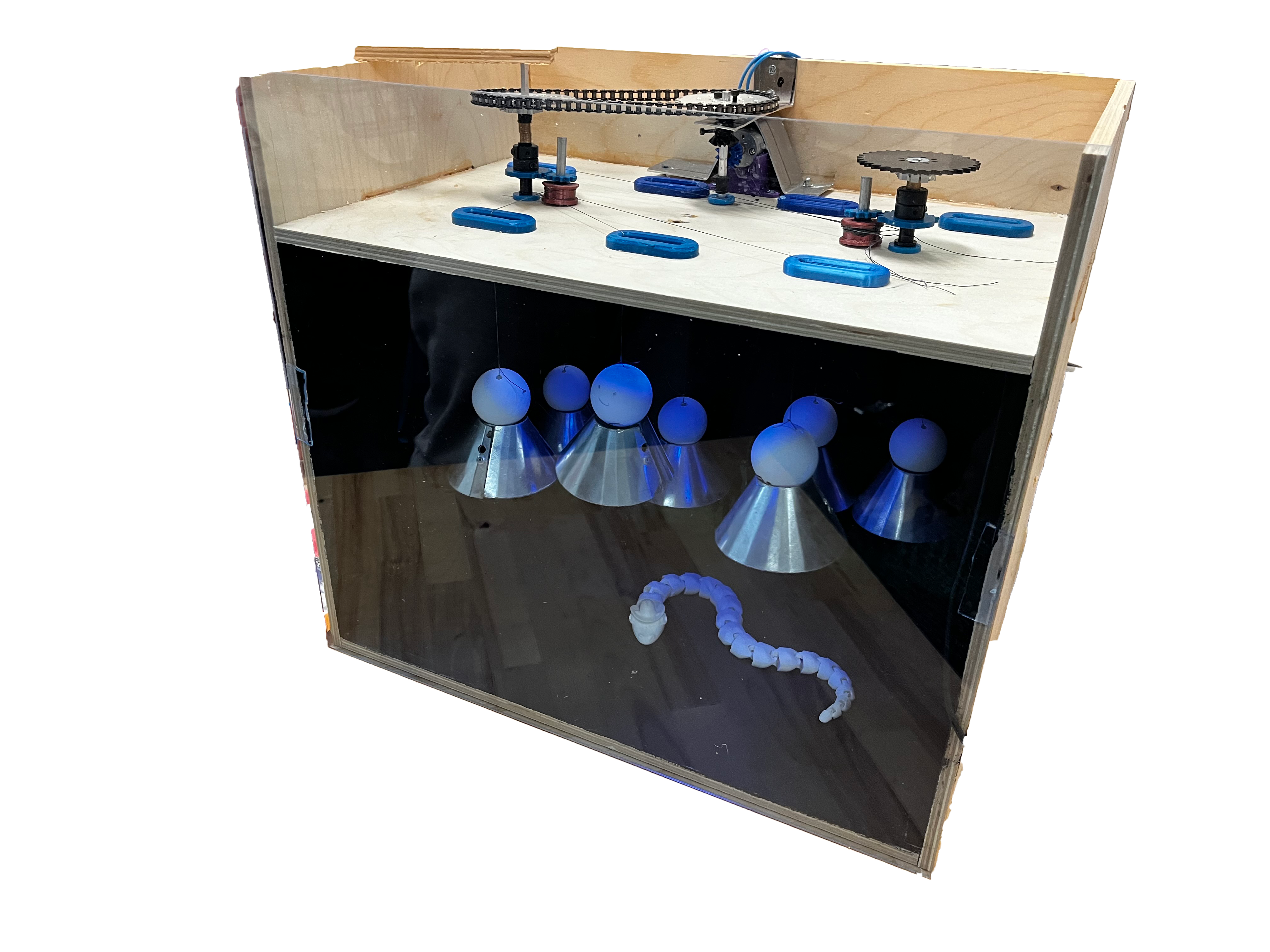
The goal of this project is to create a beautiful, decorative piece of engineering for the O, which, due to its structure, acts as a wind tunnel.
We designed, analyzed, and fabricated a wind turbine that powers a small water pump feeding a unique water feature arrangement.
Power from the blades is transferred through a belt and pulley system to a single-stage gearbox, both designed to increase the RPM to the input shaft of the gear pump.
Tubing from the output of the gear pump extends to the highest water feature and then trickles through the other elements before returning to the reservoir.
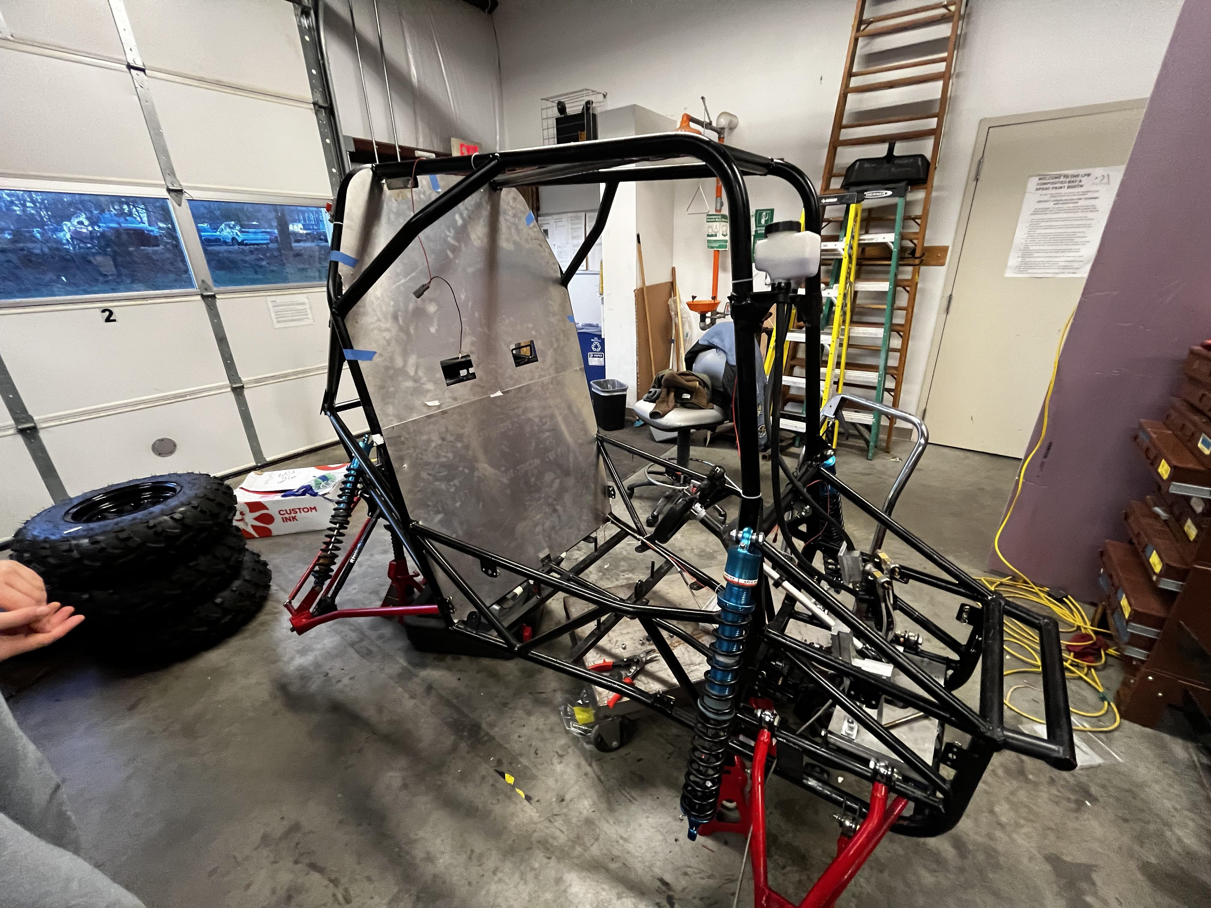
The structure is made of triangulated steel with TIG-welded legs to ensure structural integrity.
Functional Requirements:
Be able to run a cosmetic water fountain
Implement pump mechanism to power water fountain
Minimize frictional/parasitic losses and reach a minimum efficiency of 90%
Fully mechanical system
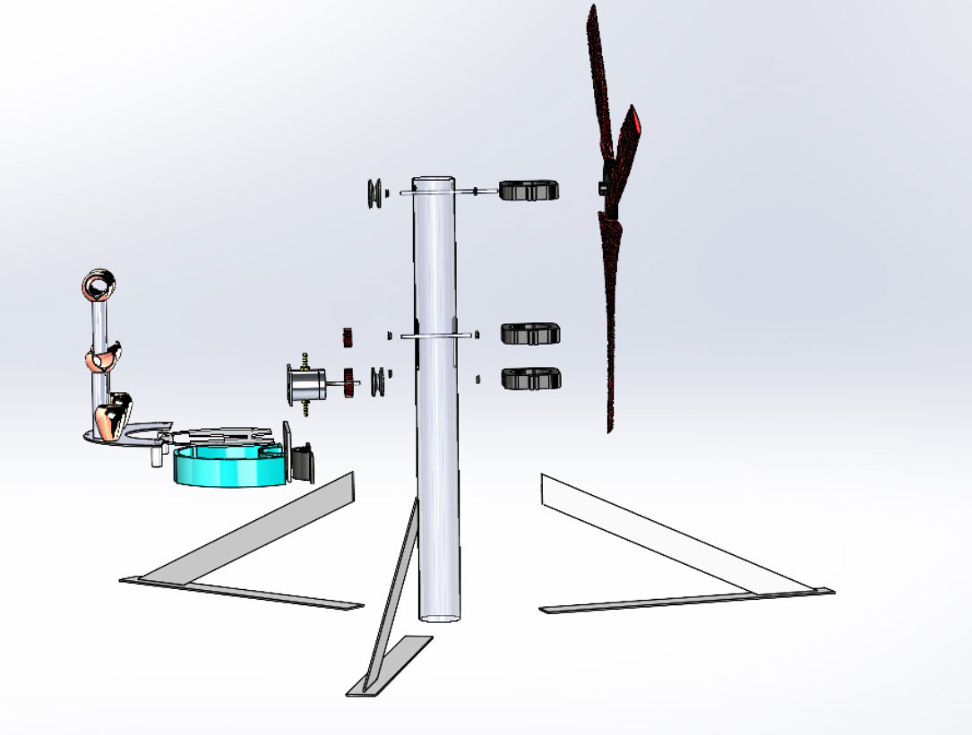
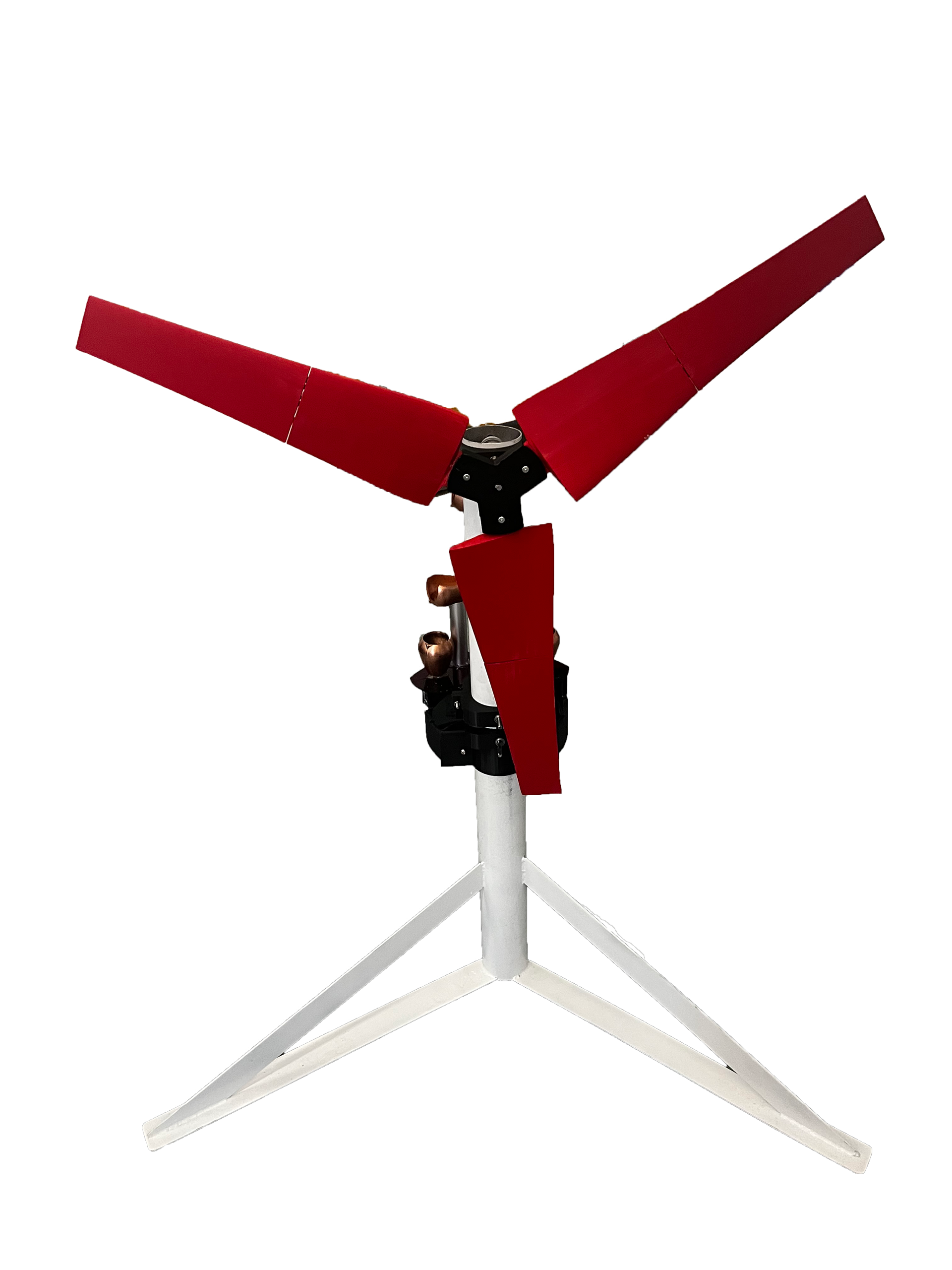
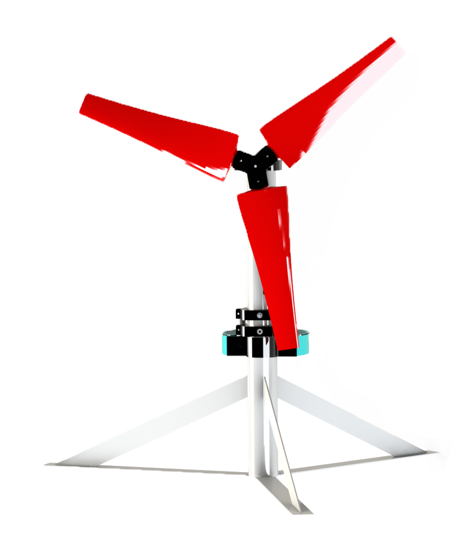
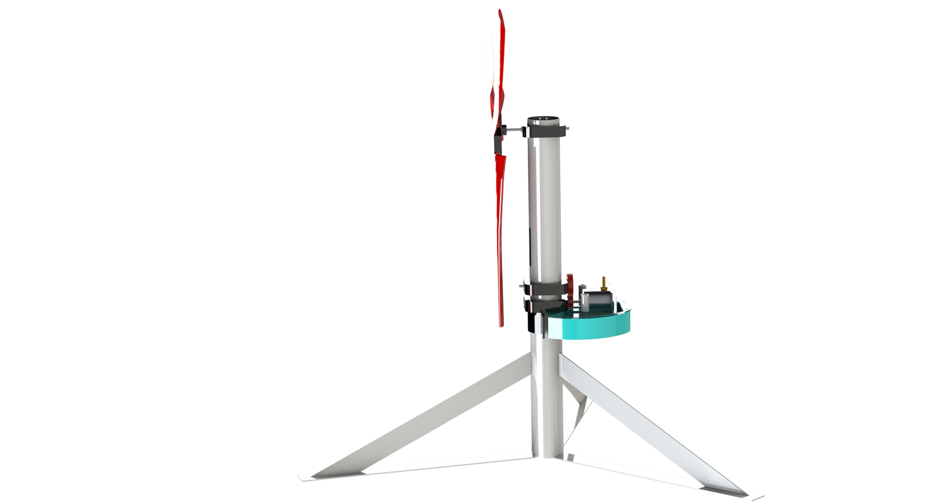
Stand and Powertrain Overview and Design Decisions
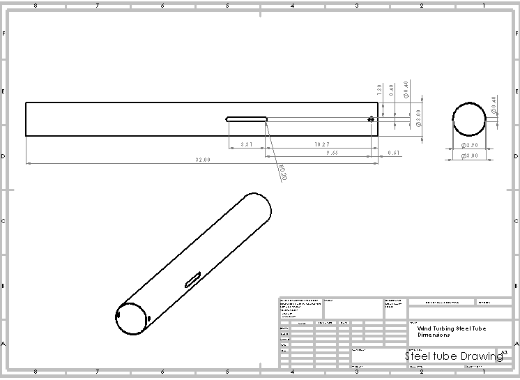
The steel tube is 36 inches long and 3 inches in diameter. As stated above, this is the main support of the turbine. This long length was chosen for a number of reasons. Firstly, we had not defined how long our wind blades would be and wanted to accommodate varying lengths. We knew that the blades were limited by what we could print on the printer and set a rough estimate of 24 inches or under for our blade lengths. Buying 36 inches of tube allowed for some variability. We could size the tube to whatever blade length we chose. The tube also has two pass-throughs—a fixed, centered hole and a slot. The hole is for the turbine to pass through, and keeping this position fixed made sense in terms of keeping the blade mount structurally sound and, for the most part, immovable. The slot was a design choice made for two different reasons. Firstly, we needed a way of tensioning our belt, and we chose not to use a belt tensioner because it would add a lot of new parts to the assembly. This was unnecessary complexity, and the slot was a much easier solution, as we could just change the shaft position to whatever belt tension felt right. Secondly, we were choosing between a lot of different gear ratios, which introduced different diameter gears and, in turn, shifted shaft positions. The slot was made long enough to accommodate a range of different gear sizes.
Gear Reduction
The gear reduction acts as the second half of our powertrain. The gears have a 4:1 ratio, making the total transmission ration 8:1 for an ideal output speed of at least 800 rpm in the pump's gears. Having two gears on the outside of the stand instead of a gear train allows for a sleeker design and lets us make less gears, which are difficult to manufacture using Olin's facilities.
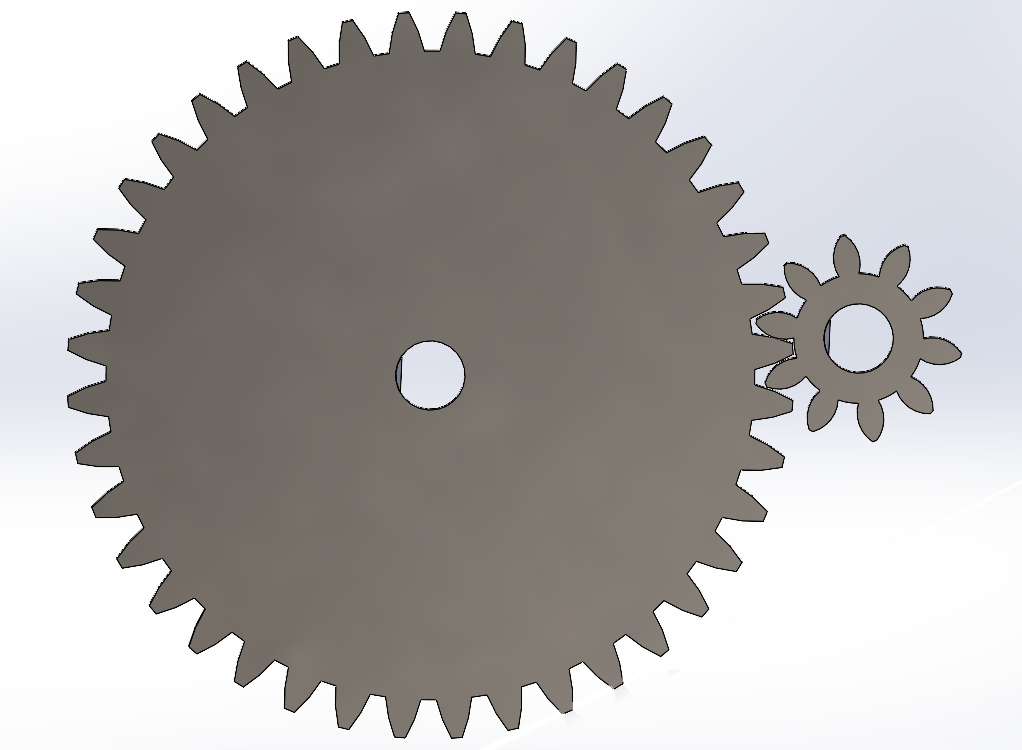
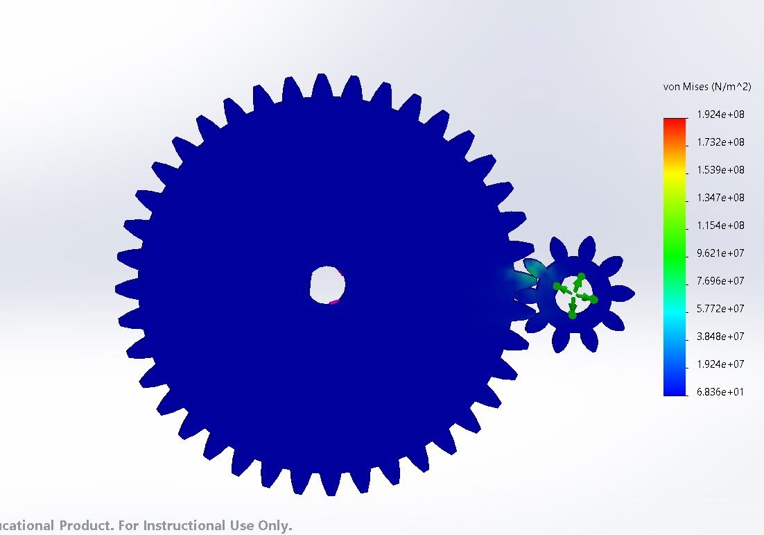
Gear Analysis
A static FEA study was conducted on the gears to ensure they would not fail due to stress. The study looked at the stress in the teeth with one 40 tooth gear driven at 0.54Nm of torque and the 10 tooth driven gear with. The study showed that the ABS gears would not fail from being driven by the pulleys and blades.